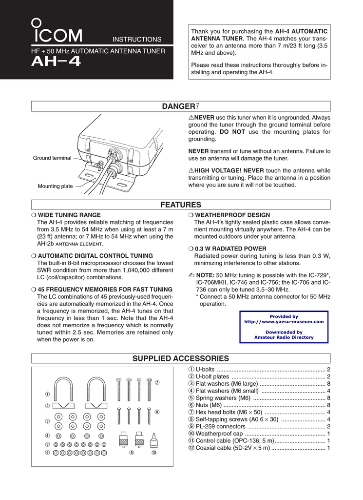
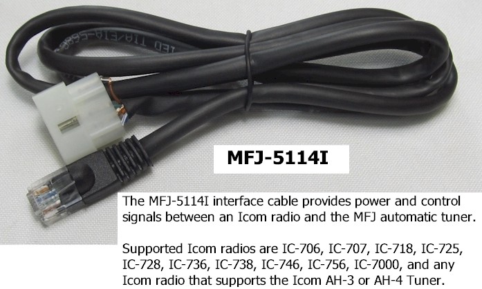
The Icom AH-4 is designed for use with all Icom HF transceivers. It stores up to 45 memory channels with minimum SWR settings to provide quick re-tuning. Weather resistant construction, easily fitted in a variety of locations. No adjustments are necessary, just connect the control and antenna cables. Tunes a wide frequency coverage from 3.5 to 50 MHz with a 7m or longer wire antenna, or the.
- Short video showing what it takes to get the AH-4 tuner from the box to operational status. AH-4 Manual Link: http://www.icom.co.jp/world/support/download/ma.
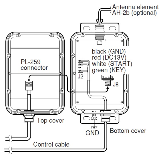
- Build a control cable for the AH-4. Build a conversion cable that is connected to the AH-4 supplied cable. When you chose No.1: Purchase a 4-conductor shielded cable and build the control cable. One side is for the J2 connector in the AH-4, the other side is for the IC.
Technical Segment
Using the Icom AH-4 with the IC-705
In this article, FB NEWS Worldwide editors are going to introduce how to use the Icom AH-4 Automatic Antenna Tuner with the IC-705. It is reported that an Icom antenna tuner especially for the IC-705 is being planned for release, but we just wanted to use a wire antenna with the IC-705 “right now.”
Please note that this is not an officially recommended method by Icom.
Pin assignments of the IC-705 TUNER jack
There is a TUNER jack on the right side of the IC-705, and according to the Icom webpage, an antenna tuner will be released in the future that can be connected to it.
Right side of the IC-705
This is a three-conductor stereo jack, and [KEY], [START], and [GND] are assigned sequentially from the tip.
Pin assignment
Connecting the AH-4 to the IC-705
Unlike the IC-7610 or IC-7300, there is no jack especially for the AH-4 on the IC-705. However, we assumed that if we connect the control lines of the AH-4 to the IC-705’s TUNER jack, and separately supply the 13.8 V DC power...the antenna tuner might work well.
When the AH-4 is connected to the IC-7300, the 13.8 V power is supplied from the radio to the AH-4.
When the AH-4 is connected to the IC-705, both the AH-4 and IC-705 must be connected to the same power supply and grounded at the same internal GND terminal.
To connect the AH-4 to the IC-705, connect the three control lines for KEY, START and GND to the tip, ring, and sleeve of a 3.5 mm stereo plug. Connect the fourth power line to a suitable power connector, which is required to supply 13.8 V DC power to the tuner. You can purchase a 3.5 mm stereo plug at a parts shop, but we also recommend trying out a screw-type connector.
Direct wiring with a screw-type connector is convenient for a trial.
Now, there are two ways to connect the AH-4 to the IC-705.
1. Build a control cable for the AH-4.
2. Build a conversion cable that is connected to the AH-4 supplied cable.

When you chose No.1:
Purchase a 4-conductor shielded cable and build the control cable. One side is for the J2 connector in the AH-4, the other side is for the IC-705 TUNER jack and the DC power supply.
The 4-conductor shielded cable we bought.
When you chose No.2:
To make a conversion cable, buy the necessary spare parts described below. Contact your local distributor for ordering details. Because the AH-4 standard supplied cable is too long for the IC-705, you can cut and shorten it if needed, but we are not responsible for any trouble that may occur.

Required spare parts:
...female, radio side
Component name: 1490R1
Icom component number: 6510001940
...4 pins are required
Component name: 1189TL
Icom component number: 6510007460
Completed conversion cable
Verifying operation
This is a screen capture before we connect the AH-4 to the IC-705. [TUNER] is grayed out.
The IC-705 FUNCTION screen before connecting
Connect both the AH-4 and the IC-705 to the same regulated power supply after turning it OFF. Then turn ON the power supply to power ON the AH-4 first, then push the [POWER] key in the IC-705 to turn ON the IC-705. This sequence is important for the AH-4 to be recognized by the IC-705. Now look at the IC-705 FUNCTION screen again to confirm that [TUNER] is no longer grayed out. Touch and hold [TUNER] for one second to turn it ON.
The IC-705 FUNCTION screen after connected
When tuning is started, the [TUNE] icon blinks red in the upper-left corner of the IC-705 screen. When tuning is complete, the icon stops blinking and is lit white.
The IC-705 screen after tuning
We look forward to seeing the Icom antenna tuner!
Now we figured out that we can use the AH-4 connected to the IC-705...but we can’t wait for the official Icom antenna tuner, to bring out the best in the IC-705!
Technical corner
Using antenna tuner AH-4 with IC-705
Shipment of IC-705 to retailers has started. The antenna tuner for the IC-705 is “to be released”, but “I want to use the wire antenna with the IC-705 soon”, so I tried to verify whether the AH-4 can be used with the IC-705.
IC-705 TUNER Jack and plug pin assignment
The IC-705 has a “TUNER jack” on the right side, and is said to be “connectable to an IC-705 dedicated antenna tuner that will be released at a later date.”
IC-705 TUNER jack position.
The TUNER plug is a 3-pole stereo plug with [KEY], [START], and [GND] assigned from the tip.
Pin assignment of IC-705 TUNER plug.
To connect AH-4 to IC-705
IC-705 does not have AH-4 connector like IC-7610 or IC-7300, but connect each control line from AH-4 side and GND to TUNER jack, and separately add 13.8V to AH-4. Once supplied, the IC-705 will also be able to use the AH-4…
Connection diagram of AH-4 and IC-7300. The AH-4 is powered by 13.8V from the radio itself.
Control Cable Inc Baltimore Md
Connection diagram of AH-4 and IC-705. Connect AH-4 and IC-705 to the same external power supply, and ground properly from the GND terminal.
Control Cable Assembly
To connect AH-4 to IC-705, connect each control line (KEY and START) and GND line from AH-4 side to the tip and ring of Φ3.5 stereo plug so that 13.8V can be supplied separately. To process. You can get a Φ3.5 stereo plug at a parts shop, but if you just want to verify the operation, a screw-type conversion connector is convenient.
The screw-type conversion connector that can be wired directly to the 3-pin terminal is convenient for wiring confirmation.
To connect the IC-705 and AH-4, prepare either of the following cables.
(1) AH-4 control cable that is specially processed for IC-705 connection using Φ3.5mm plug.
(2) A conversion cable to be attached to the AH-4 control cable connector using the AH-4 connector (female side) parts.
In the case of (1), the control cable attached to the AH-4 will be processed, so I would like to avoid this, and use one side of the separately purchased 4-core shielded cable as the J2 connector of the AH-4 and the other side. Processed so that it can be connected to IC-705. (Red part of the above connection diagram)
The purchased 4-core shielded cable. It can be purchased in units of 1m, and there is a discount if it exceeds 10m.
In the case of (2), a cable of several tens of centimeters is sufficient, so if there is no problem with shortening the control cable that comes with the AH-4 standard, cut the required length from the AH-4 main unit side before using. Would be fine. The shell and pin of the AH-4 side connector (female side) of the conversion cable can be requested for purchase (cash on delivery) from the Icom Support Center mail form.
Parts for AH-4 connectors can be ordered from the Icom Support Center mail form.
A conversion cable that I made by ordering the AH-4 connector (female side) parts.
Connection and operation check
Since the IC-705 has not arrived at hand, I borrowed the display machine of the ham shop to check the operation. When checking the IC-705 function screen before connecting the AH-4, it is natural that [TUNER] cannot be selected.
IC-705 function screen before AH-4 connection.
Next, connect both AH-4 and IC-705 to the same stabilized power supply with the power off, and turn on the power in the order of AH-4 → IC-705. When I checked the function screen of IC-705, the text [TUNER] was displayed in white this time, and when I touched it for a long time (about 1 second), it changed from OFF to ON.
IC-705 function screen after connecting AH-4.

When tuning is started with the external antenna tuner, the [TUNE] display flashes red in the upper left of the IC-705 screen, and when tuning is completed, the [TUNE] display changes to lit.

TUNE display on the upper left of the IC-705 screen. When tuning is done, it lights up as shown in the figure.
Precautions when using the AH-4 and expectations for a dedicated antenna tuner
By connecting AH-4 to IC-705, it was confirmed that it works theoretically. I was able to tune without any problems, but it seems that there are some bands whose detection of tuning completion is more severe than other radios. The tuning power of the AH-4 is 10W, and the instruction manual for the AH-4 also states “If you are using a 10W machine, set the transmission output to high power (10W).” In conclusion, I feel that it is possible to operate with IC-705 connected to AH-4, but it is also necessary to divide it from provisional operation.

The IC-705 is compact and can be operated with a battery. In order to maximize the enjoyment, I wanted a dedicated antenna tuner as soon as possible!
At the summit of Asahidake, Hokkaido. I used RH-770 to communicate with ID-51 in the 144MHz/430MHz band.
With the IC-705 and a dedicated antenna tuner, the fun of wireless is likely to spread.
Enjoy the RICE CRACKERS AND LANTERN